keytrond
Pipe Bending Machine Connecting Blocks

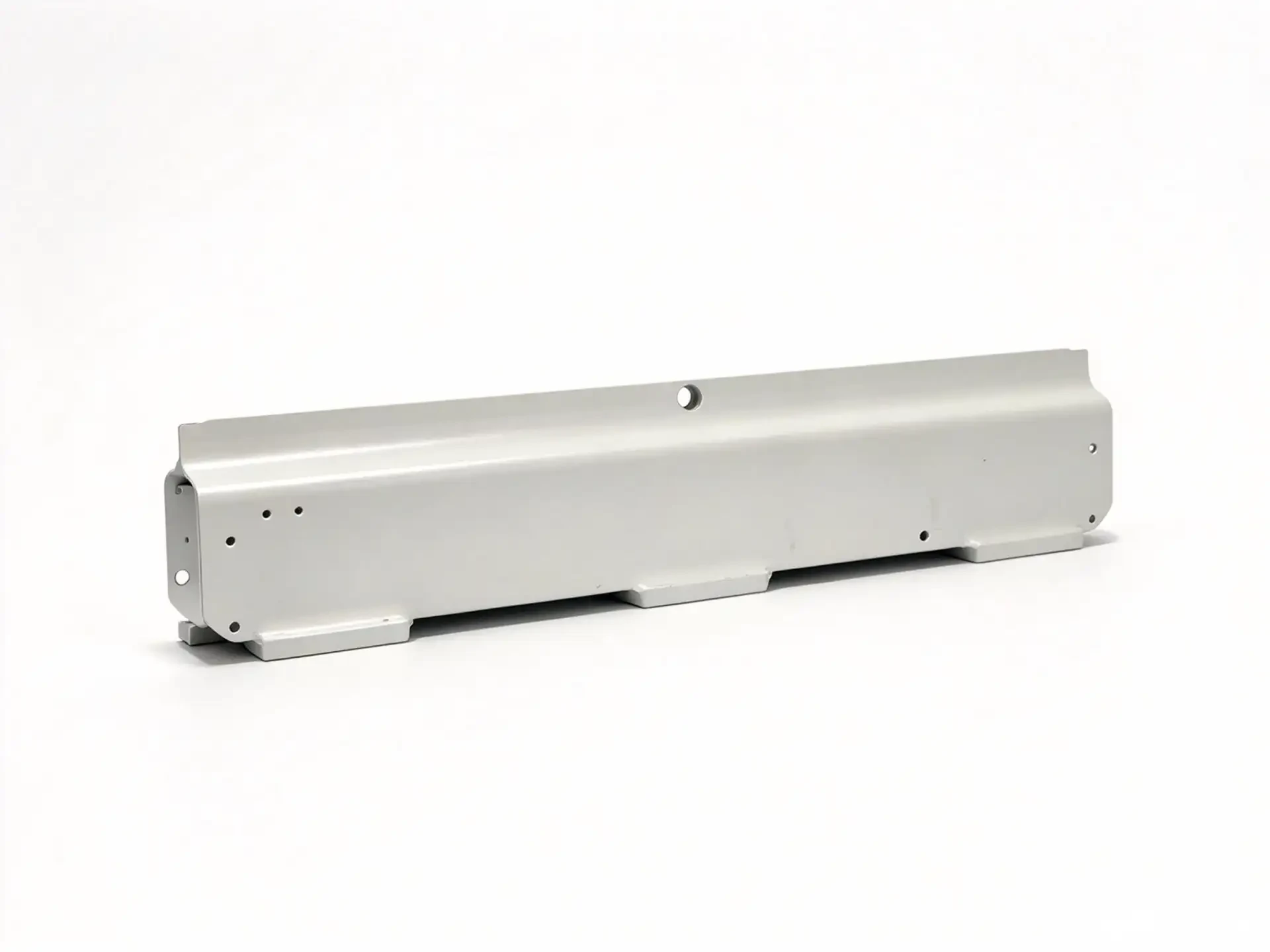
Aluminum Connecting Block

Aluminum connecting block milled from billet for pipe bending machines, with flat mating faces and anodized finish.

Tolerance
IT7 - IT8, flatness 0.05 mm
Lead time
Sample 5-7 days, batch 10-15 days
Pipe Bending Machine
Contact the factory
Technical parameters

Machining parameters for this part

Values below are the standard range keytrond holds for this part family. Tighter requirements are reviewed against the drawing before quotation.

Aluminum Connecting Block technical parameters
Tolerance rangeIT7 - IT8, flatness 0.05 mm
Surface roughnessRa 1.6
Common materials6061-T6, 7075-T6
Surface treatmentAnodizing, Hard anodizing, Bead blasting
Machining processesCNC Milling, CNC Turning, Surface Finishing
Max machining size300 × 200 × 150 mm
Applicable industriesPipe Bending Machine
Minimum order5 pcs for sample, 100 pcs for batch
Lead timeSample 5-7 days, batch 10-15 days
Drawing requirementPlease mark mating faces, bore and hole tolerance, anodizing colour and film thickness.
Process notes

How this part is machined

Connecting blocks join the bending arm, guide and frame on a pipe bending machine. Aluminum is used where the block is a locating element rather than a load bearing part, because it keeps weight down and anodizes to a clean finish.

The block is milled from 6061-T6 plate. The outer form is roughened, then the part is released and finished with the mating faces and bores in one clamping. After deburring, chamfering and anodizing, each block is checked for flatness and hole position.

Machining points

Process measures behind the tolerance

  1. 01Mating faces milled in one setupBoth mating faces and the locating bore are finished in the same clamping so the block sits flat on the machine frame.
  2. 02Light weight with stable facesAluminum is milled with staged finishing passes after a stress pause, so thin sections stay flat after anodizing.
Inspection

Inspection items and methods

Inspection itemMating face flatness
Method and instrumentSurface plate and height gauge
Inspection itemHole and bore position
Method and instrumentCoordinate measuring machine
Inspection itemCoating thickness
Method and instrumentFilm thickness gauge, 10-15 μm

A first article inspection report with dimensional results, material certificate and heat treatment record is provided for sample orders. Batch orders are sampled at 10 percent, with full inspection available on request.

Related parts

Other parts in this family

All products
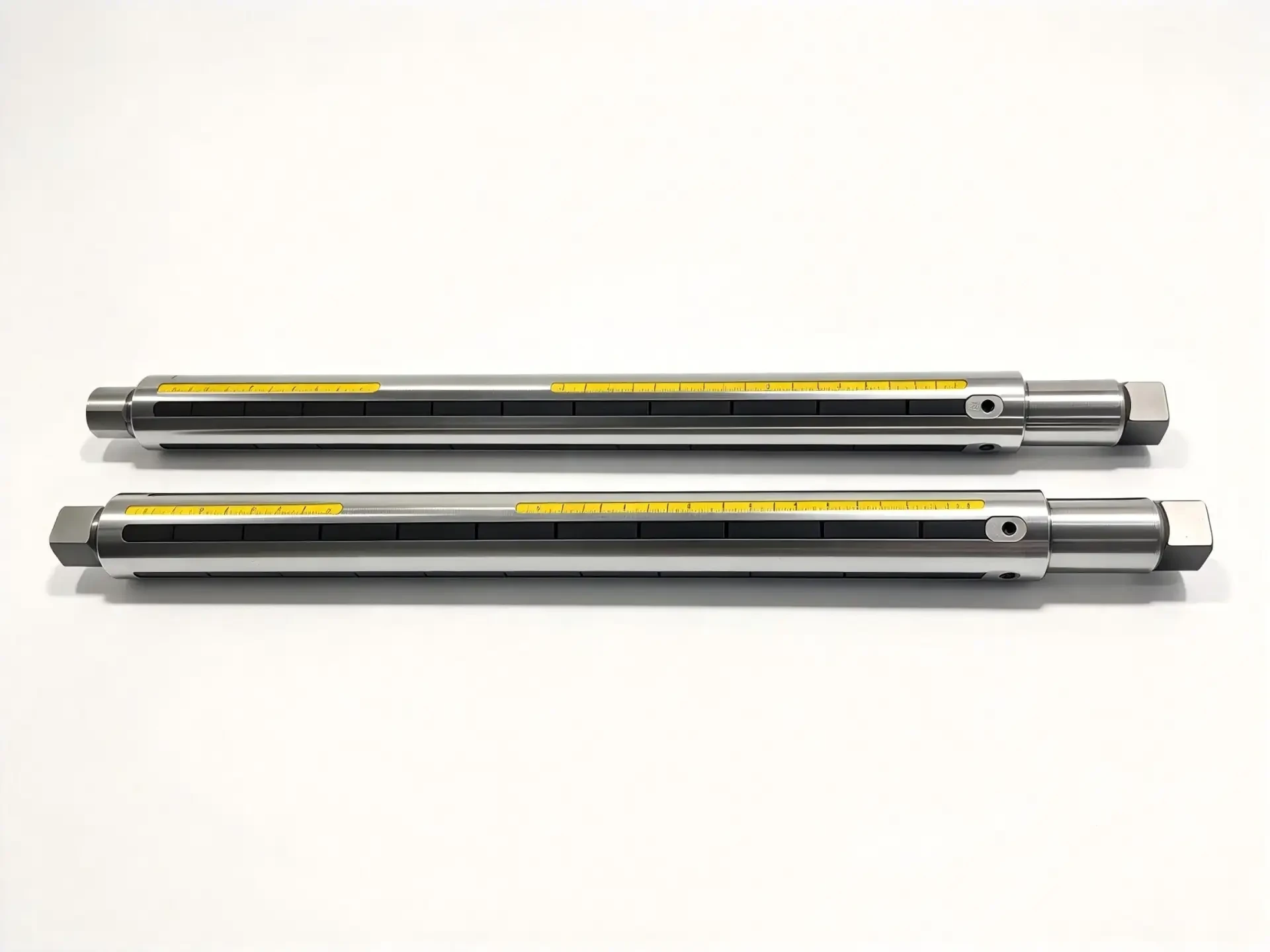
Ruler AxisShafts

Ruler Axis

Precision ground shaft used as a linear measuring and guiding element, with controlled straightness over full length.

Tolerance
Ø IT6, ±0.005 mm
Materials
GCr15, 40Cr, 45#, SUS304
Surface
Hard chrome plating
Glass MachineryWoodworking MachineryGeneral Automation
Parameters
Glass Machinery Precision Welded PartGlass

Glass Machinery Precision Welded Part

Welded and machined assembly in 45# steel and QT500 ductile iron for glass processing lines, finished with industrial paint.

Tolerance
IT8 - IT9, mounting faces ±0.1 mm
Materials
45#, QT500-7
Surface
Painting
Glass MachineryGeneral Automation
Parameters
Stainless Steel 304 Welded PartGlass

Stainless Steel 304 Welded Part

Stainless steel 304 welded assemblies for glass machinery, blow molding and injection molding lines.

Tolerance
IT8 - IT10, frame squareness ±0.2 mm
Materials
SUS304, SUS316L
Surface
Passivation
Glass MachineryBlow Molding MachineInjection Molding Machine
Parameters
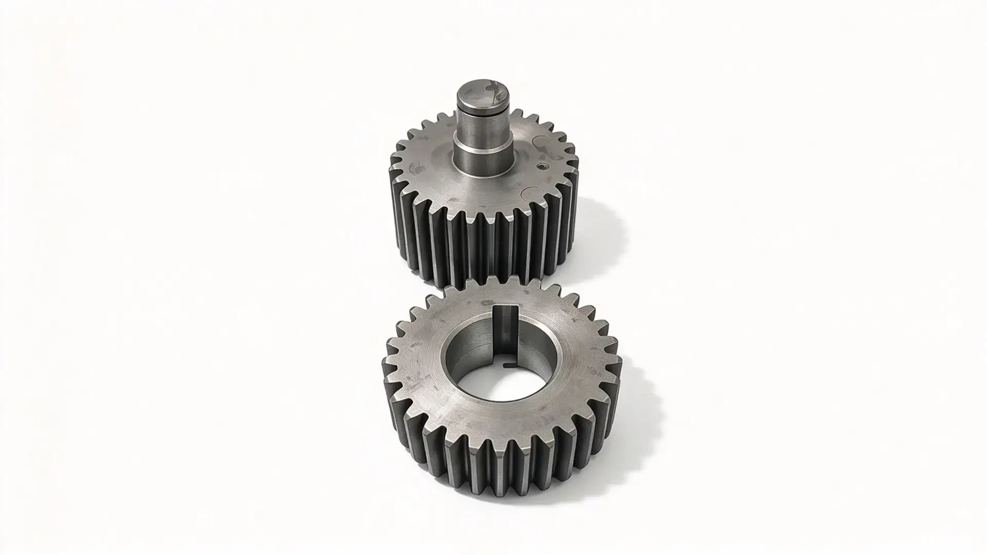
Precision GearsGears

Precision Gears

Spur and helical gears in alloy steel, carbon steel, bronze and POM, cut and ground to GB/T 10095 grade 6 to 8.

Tolerance
GB/T 10095 (ISO 1328) , Accuracy Grade 6~8; Bore Tolerance: IT6
Materials
20CrMnTi, 40Cr, 45#, POM, ZCuSn10P1
Surface
Carburizing and quenching HRC 58-62
Glass MachineryBlow Molding MachineGeneral Automation
Parameters